Simple mount for TLPHnodeV2
The pressure sensor on the TLPHnodeV2 is light sensitive and needs a cover. I’m not ready to commit to a full enclosure, so I designed a simpler cover for board bring-up and evaluation. The cover was designed using FreeCAD and is being printed at Shapeways.
I am using FreeCAD because it is available on Ubuntu, OpenSource, and I can import a model of the PCB from KiCAD in order to visually check my design. FreeCAD is quite a flexible tool with a fair bit of complexity. However the documentation is good and there are a number of tutorials on YouTube.
One important detail of the mount design is that the board size reported by KiCAD and the PCB fab house are slightly different (28.0x20.5 mm in KiCAD vs 28.22x20.70 mm). FreeCAD supports parametric models, so I did the design based on the KiCAD numbers, checked the fit against the 3d model exported from KiCAD and then changed the mount dimensions before sending it to the printer.
KiCAD to FreeCAD
The KiCAD version I am using, no-vcs-fount-7448-57-ubuntu16.04.1,
release build , exports models in several formats. FreeCAD, version
0.16 for Ubuntu 16.04, will read three of them: IDFv3(.emn),
VRML(.wrl) and STEP(.stp). I found the STEP model to be a bit
difficult to work with because the elements of the model were independ
and it was easy to inadvertently move them. The IDFv3 was a model of
just the PCB and did not include the components. So I used the VRML
model.
The downside of the VRML model is that it I could not find a way to reference faces and edges from the model in my FreeCAD design. The wasn’t too much of a problem since I was going to use a parameter spreadsheet for the key measurements so that design could be scaled to the actual board dimensions.
I made a point of locating one corner of the KiCAD PCB model at 0,0,0 so that it would be easy to align the PCB model and the mount design. This required two steps. The first was to export the model from KiCAD with the proper offset and the second required adjusting the z-axis offset of the PCB model when it was loaded into FreeCAD.
Since I use a page title block in my KiCAD designs, the PCB is typically
not located at 0,0. To adjust for that when exporting the model, look up
the coordinates of a corner of the board outline and use those values as
X Ref and Y Ref the VRML export dialog:
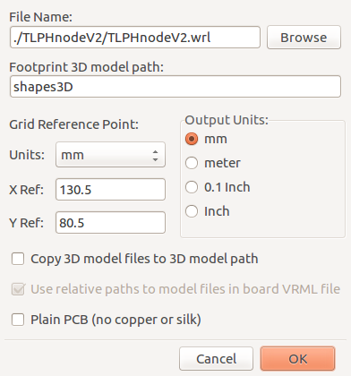
Since there is not a Z Ref adjustment on export, I moved the model 1/2
the board thickness (1.6mm/2= 0.8mm) when I located it in FreeCAD. Now
one surface of the board is located at Z=0 and I can start my design by
drawing a sketch in the X/Y plane.
FreeCAD Parametric Design
This section is not a substitute for the documentation or tutorials.
Measurements and parameters that might be changed are entered into a spreadsheet:
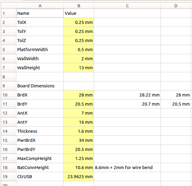
The cells in yellow (values in Column B) have a parameter name assigned.
To make it easy to find the parameter names, I recorded them in Column
A. In order to use the parameter, the spreadsheet name and the parameter
name are combined. For example (the spreadsheet in this case is
imaginatively named Parameters):
Parameters.BrdX
The values in the spreadsheet can be changed at anytime and the design will be automatically updated.
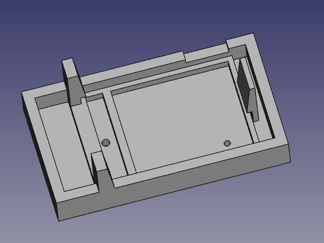
Mount details
Since the light sensor needs to be exposed, but light needs to be kept away from the pressure sensor, the mount needs to create a dark area for the pressure sensor. I wasn’t sure if the humidity sensor was light sensitive, so I put it in the dark area.
The board rests on a 0.5mm wide shelf and a bar runs between the light sensor and the pressure sensor. This required a bit of planning during the PCB layout so that there was clear space to run the light blocking bar. I also make it a point to locate the light sensor on the center line so that it would be easier to align a hole with it.
I want the latch at the connector end of the mount to be flexible so that the board will snap in place. However I don’t have enough experience with the printed material to know if my design will work. Likewise the tolerances I used are just educated guesses at this point.
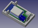
Visual inspection
Visual inspection can catch a lot of interference problems, but it is not a panacea. Here is the view I used for the inspection. There is a problem, but I didn’t catch it:
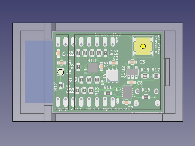
The problem is the hole for the reset switch (yellow component). There is no baffle between the hole, which could let some light in, and the pressure sensor (U3).
I discovered the error while writing up the description in the Mount Details section, but only after I send the mount to be printed. It is not a huge error and the fix is to simply cover the whole with black tape most of the time, so I expect the mount to still be usable.
The lesson here is that designs need to be reviewed, and not just by the designer. Even preparing a description for someone else can uncover problems that are easy to over look!
Subscribe
Subscribe to this blog via RSS.
Categories
Firmware 1
Hardware 5
Console 1
Tools 4
Recent Posts
-
 Posted on 16 Jan 2017
-
 Posted on 12 Jan 2017
-
Posted on 24 Jan 2016
-
Posted on 19 Jan 2016
Popular Tags
Background (2) Firmware (1) Hardware (5) Infrastructure (1) Console (1) T&l node firmware (1) Tools (4) Tlphnodev2 (2)

